Microservices architecture is built on top of a distributed system in which you can see many services, standalone CronJobs, third-party dependencies, and so on. Since there are many challenges in such an environment, it is important to build cloud-native applications. Container technologies like Docker help generate cloud-native artifacts from those application source codes. In the same way, Kubernetes, an open source container orchestration platform, helps deploy artifacts in an environment in which most of the cloud components, such as a load balancer, disk, and networking, are abstracted. In this chapter, we will learn how to build artifacts within the CI (continuous integration) pipeline and deploy gRPC microservices to Kubernetes in the CD (continuous deployment) pipeline.
Docker is a platform that helps you to build and package your application and its dependencies, as well as deploy it seamlessly. (See this book to learn more: https://www.manning.com/books/docker-in-action-second-edition.) Here, I will skip the basics and provide practical information. Building a Docker image for a Go application is easy since we simply add a Go binary executable into the Docker image, and it already has all the dependencies we need inside it. This executable will be the container’s entry point, a runnable instance of the Docker image, so that it will launch our application whenever you run a container. To better understand this process, let’s look at how we can build a Docker image for our microservices.
Building a Docker image has two steps:
In the Dockerfile, a line should start with the FROM keyword to state our application’s parent image. In Go, there are different dependencies for compile time and runtime. For example, we need to be able to run go build to generate a Go binary executable, but once we build it, we no longer need the Go distribution in the container runtime. We can provide a generated Go executable binary as an entry point to the Docker container. Separating compile time and runtime dependencies in Docker images is the process of creating multistage builds in Docker (see https://docs.docker.com/develop/develop-images/multistage-build/). In the example that follows, a Golang Docker image will be the parent image that executes the go build command, and we will pass a generated artifact to the next stage, which uses a scratch Docker image as the parent. The scratch image is a special one that you cannot pull or run as a standalone container but that you can use as a parent and provide an executable as an entry point:
FROM golang:1.18 AS builder                                           ❶
WORKDIR /usr/src/app
COPY . .                                                              ❷
RUN CGO_ENABLED=0 GOOS=linux go build -a -installsuffix cgo -o order
➥ ./cmd/main.go                                                      ❸

FROM scratch
COPY --from=builder /usr/src/app/order ./order                        ❹
CMD ["./order"]                                                       ❺
❶ Uses the Golang Docker image as parent
❷ Copies Go source code to the Docker image
❸ Builds a Go binary executable
❹ Copies a generated artifact from the first stage to the second one
❺ Orders a gRPC server as an entry point
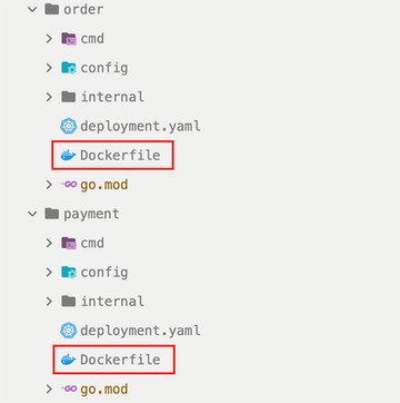
Now you can create a Dockerfile under the Order service in the microservices project (order/Dockerfile) and add this content. We will soon use this to prepare our Docker image. Notice that you can create one more Dockerfile for the Payment service. Just replace the order with a payment, then put that in the payment/Dockerfile file (figure 8.1).
Since we have a Dockerfile for each service, we are ready to build Docker images as follows:
docker build -t order.
If you execute this command while you are in the order folder, the current folder will be in Docker context (since that is the location of the Dockerfile) and a local Docker image will be built for you, but it should be published to a remote registry, a storage system in which you can store your Docker images so that Kubernetes can pull them. The most popular Docker registries for production environments follow but in this chapter, we will not use registries; we will copy the Docker images to Kubernetes cluster nodes to have faster development feedback:
You can also install the on-premises version of Docker registries in your network for better performance during pull and push operations. If you are using Docker Hub as your Docker image registry, you can use the following command to push your images after you tag them:
docker tag order huseyinbabal/order:1.0.0
docker push huseyinbabal/order:1.0.0
Now that we understand how to build Docker images for our Go microservices let’s get familiar with our deployment environment, Kubernetes. Docker registry providers require a valid authentication token you can get via a docker login command. Of course, in the Kubernetes environment, we can provide a pull secret since running the Docker command while deploying microservices is not feasible.
Kubernetes (i.e., k8s) is an open source container orchestration platform that helps manage containerized workloads or services. Kubernetes has a good abstraction layer, a virtualized logical operating environment that utilizes physical hardware infrastructure components such as disks, networks, and machines. For example, once Kubernetes is deployed on a set of machines, an internal service discovery mechanism is provided so that you don’t have to worry about IP addresses in a networking context. Microservices can interact with their service names.
Now that we understand what a Kubernetes cluster is, let’s look at its core components. Since Kubernetes is a popular open source platform, you can see it in almost all cloud providers; you can go to their consoles and spin it up with one click. In the same way, you can include Kubernetes cluster installation in your infrastructure as a code pipeline to provision clusters with Terraform or other cloud provider–specific SDKs such as eksctl (http://mng.bz/Gye8). In the cloud environment, you can use AKS, Azure-managed Kubernetes; EKS, AWS-managed Kubernetes; or GKE, Google Cloud–managed Kubernetes. If your services are on bare metal servers, Kubespray is also an option (https://github.com/kubernetes-sigs/kubespray).
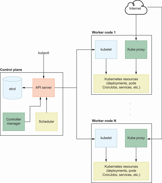
A Kubernetes cluster is a distributed system made from a machine set that contains primarily containerized workloads. Those nodes are divided into control plane nodes and worker nodes. The control plane is the brain of the Kubernetes cluster, and it has mission-critical components to manage resources in the Kubernetes environment. Those resources are specific to Kubernetes, but they manage a containerized application under the hood. Worker nodes contain system components like kubelet and workloads like pods, the minimum deployable unit in Kubernetes (see figure 8.2).
Let’s look at a simple explanation of each component:
kubectl—This is the command-line application for Kubernetes, that allows you to manage your resources and Kubernetes cluster nodes. Its primary responsibility is to provide a simple interface to the end user while interacting with the API server in the control plane.
API server—This is the Kubernetes cluster API endpoint that provides unified access to end users for Kubernetes management. You can manage your Kubernetes resources or maintain Kubernetes nodes through this component with the help of kubectl.
Scheduler—Whenever you try to deploy a pod (the minimum deployable unit in Kubernetes), it will be scheduled to an available node based on resource requirements.
Controller manager—This component manages the controller processes available in Kubernetes, such as ReplicationController. Whenever there is a change for a resource definition, ReplicationController detects it and applies it to a specific resource to create the desired state. This can be a replica count change, Docker image change, and so on.
etcd—This is used to store resource states in the Kubernetes environment. Whenever you create a pod, the metadata is stored in etcd first, and then the scheduler handles the remaining part to schedule it to the available node.
kubelet—This worker node component is in contact with the API server, and its primary responsibility is to track the state of pod specification. It continuously checks the pod, ensures underlying containers are healthy, and reports to the control plane.
kube-proxy—This component exposes services to the outside once they are needed, allowing each service to communicate through a special internal discovery system.
NOTE You will see many examples related to Kubernetes resource operations for deploying microservices. You can try all of them locally using Minikube, a local Kubernetes cluster that helps you learn and try out Kubernetes (https://minikube.sigs.k8s.io/docs/start/). You can also use kubectl, a command-line tool that allows you to run commands against a Kubernetes cluster (https://kubernetes.io/docs/tasks/tools/#kubectl).
Now that we understand the components of a Kubernetes cluster, let’s look at what kind of resources are available and how they work.
You can’t deploy containers to the Kubernetes cluster directly because there is an abstraction on top—a pod, a minimum deployable unit that helps you define the containerized application and its environmental configurations and claim disks, once they are needed. We talk about specifications like pod specification: YAML definitions that contain information about cloud-native applications. It has three mandatory fields: apiVersion, kind, and spec. apiVersion maintains versioning inside the API server. kind is for defining the resource type, such as Pod, Deployment, Cronjob, Service, etc. spec is the most important specification because it contains the metadata of the application you want to run on the Kubernetes environment. In this section, you can define the characteristics of a workload as follows:
You can either statically pass environment variables with their values or pass them from a Kubernetes Secret or ConfigMap. Secrets store confidential values in base64 encoded format, and ConfigMap maintains configurations in a key-value format.
You can define how much memory or CPU reservation you need for your application.
You can specify what the behavior should do when the application crashes.
Let’s look at real-life microservices examples by diving deep into widely used Kubernetes resources we can use during application deployment.
Assume that we already have a Docker image for each microservice that we can run as a container by providing the minimum required configurations. If we use only Docker in our machine, we would run that service as follows:
docker run -d \                              ❶
    -e APPLICATION_PORT=8080 \               ❷
    -e PAYMENT_SERVICE_URL=payment:8081 \    ❸
huseyinbabal/order:1.0.0                     ❹
❶ Runs the application in the background
❷ The Order service runs on 8080.
In Kubernetes, instead of directly running a containerized application, we deploy a pod that encapsulates the container runtime. This might seem like an unnecessary encapsulation, but maybe you already know Kubernetes used the Docker engine as the default container runtime for a while, then removed it with the release of Kubernetes 1.24. If Kubernetes had a direct dependency on the Docker engine, it would be hard to migrate our Kubernetes workload if we wanted to upgrade to Kubernetes 1.24 from earlier releases. However, as you can see in figure 8.3, there are pods for the actual application workloads Kubernetes handles.
By default, pods are closed boxes; if you want to expose them to the public internet, use Services, which helps expose pods as an endpoint inside Kubernetes. If you access that endpoint with a particular path, you can use Ingress to define the path and map service to route traffic. Finally, suppose you want to make those paths available outside with automation. In that case, the Ingress controller creates a load balancer and points it to an nginx instance that contains all the pod Ingress configurations. Now that we understand the practical details behind Kubernetes resources, let’s dive deep into each one and examine them with real-life examples.
In this section, we will write down our requirements to get the Order service up and running, then try to create pod specification by referring to its requirements:
apiVersion: v1
kind: Pod
metadata:
  name: order
spec:
  containers:
  - name: order
    image: huseyinbabal/order:1.0.0
    env:
      - name: APPLICATION_PORT
        value: "8080"
      - name: "PAYMENT_SERVICE_URL"
            value: "payment:8081"
If we save this as order.yaml and execute
kubectl apply -f order.yaml
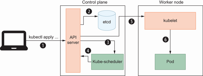
kubectl will generate a payload using this YAML content and push it to the Kubernetes API server. The API server will save this metadata into a state store, etcd in our case; then it will be scheduled by the kube-scheduler onto an available node. After the kube-scheduler assigns this pod to a specific node, kubelet will pull the Docker image specified in the image file and run the container with environment variables provided under the env section. We will use other Kubernetes resources, such as Deployment and Service, but in general, the resource scheduling flow described is the same (see figure 8.4).
Figure 8.4 is a typical pod deployment flow with just one instance of a service. However, we may need more than one instance in real life for availability. Let’s look at what kind of Kubernetes resources we can use for multiple instances of the same pod template.
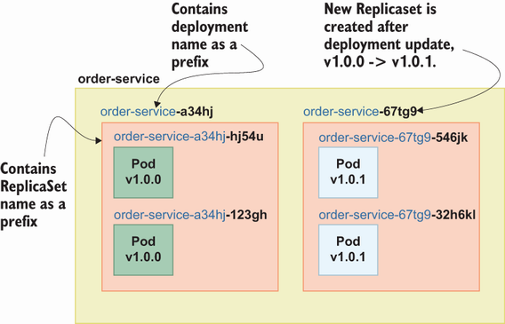
A Kubernetes resource that ensures the specified number of Pod replicas are available at any time is called ReplicaSet (https://kubernetes.io/docs/concepts/workloads/controllers/replicaset/). For example, you can have three instances of the Order service, two instances of the Payment service, and one instance of the Shipping service based on your requirements. Even though you can use ReplicaSet to directly manage the instances of a given pod, it is suggested that you also use Deployment to cover other requirements such as updating a policy. For example, suppose you want to use ReplicaSet to deploy Order service v1.0.0 and upgrade it to v1.0.1. In that case, you must create a new ReplicaSet with Order service v1.0.1 and a downscale ReplicaSet with version v1.0.0. If you use deployment to manage your actual pods, you don’t need to maintain ReplicaSets; you just need to update the image version, and deployment will handle the remainder for you. If you create a deployment with name order-service, deployment will create Replicaset order-service-<replicaset-suffix> and ReplicaSet will create order-service-<replicaset-suffix>-<pod-suffix> (see figure 8.5).
Assume that this time we want to deploy the Payment service with the following requirements:
It has an APPLICATION_PORT environment variable with a value of 8081.
It has a DATA_SOURCE_URL environment variable with a value of root:changeit@tcp (mysql:3306)/payments.
Then, we can use the following YAML file to submit to Kubernetes with the kubectl apply command:
apiVersion: apps/v1
kind: Deployment
metadata:
  name: payment         ❶
  labels:
    app: payment        ❷
spec:
  replicas: 2           ❸
  Selector:
    matchLabels:
      app: payment      ❹
  template:
    metadata:
      labels:
        app: payment    ❺
    spec:
      containers:
      - name: payment
        image: huseyinbabal/payment:v1.0.2
        env:
          - name: APPLICATION_PORT
            value: "8081"
          - name: DATA_SOURCE_URL
            value: "root:changeit@tcp(mysql:3306)/payments"
❷ Labels are good, especially for filtering.
❹ Applies to pods with those labels
❺ Each pod instance will have these labels.
You can see the labels section in all kinds of Kubernetes resources, which are primarily used for grouping resources and filtering once that is needed. The spec section shows the replicas definition, which decides the replica count of pod instances, which are inherited from the template, as seen in the template field. Finally, in the inner spec section, you can see the actual pod specification that will be applied to all instances of the pod. To create a deployment, you can save this YAML content in a deployment.yaml file in the payment folder and execute the following:
kubectl apply -f deployment.yaml
You can verify this by getting the pod status and listing deployments, or getting the details of a specific pod, as follows:
kubectl get deployments
# or
kubectl get deployment payment -o yaml
We just created a deployment, and it also created the required ReplicaSet and pod. This pod contains the workload, the Payment service, in our case, but how can we access this service as an end user? Let’s look at the possible ways to do this in Kubernetes.
Once a pod is deployed on a worker node in Kubernetes, by default it cannot receive traffic from outside. To create outside exposure, you can use the Service resource, which acts like a gateway between the client and the actual pod in the Kubernetes environment. A client, which can be a public user, can also be inside Kubernetes. Both scenarios can be achieved with different Kubernetes Service types. For example, if you want to expose the Shipping service to Kubernetes internally, you can use the ClusterIP type of Service. If you expose it outside of Kubernetes, we have two options, LoadBalancer and NodePort. Let’s look at examples to better understand the logic behind these types.
Once the LoadBalancer Service type is used, it provisions a load balancer based on cloud provider metadata. For example, if you create a LoadBalancer type Service in AWS, it can create an AWS load balancer. The Kubernetes cloud plugins handle this operation, and you don’t need to deal with cloud provider internals because there is good abstraction in Kubernetes for this kind of operation. Once the LoadBalancer Service type is successfully created, you can use the newly created load balancer URL to access the pod behind that Service.
If we use the NodePort Service type, then the pod behind that Service will be available to the public through a specified port in the Service YAML definition. For this use case, you need to know the physical IP address of at least one of the worker nodes. Finally, you can access the pod by using its URL in the following format <public_ip_of_worker_node>:<port_in_service_definition>.
Assume we want to expose the Payment service we deployed in the previous section as a load balancer to the public user:
apiVersion: v1
kind: Service
metadata:
  name: payment
  labels:
    app: payment
spec:
  selector:
    app: payment          ❶
  ports:
    - name: grpc          ❷
      port: 80            ❸
      protocol: TCP       ❹
      targetPort: 8081    ❺
  type: LoadBalancer      ❻
❶ Routes traffic to the pod with the label “app: payment”
❸ Public port on the load balancer
❺ Internal port of the Payment service
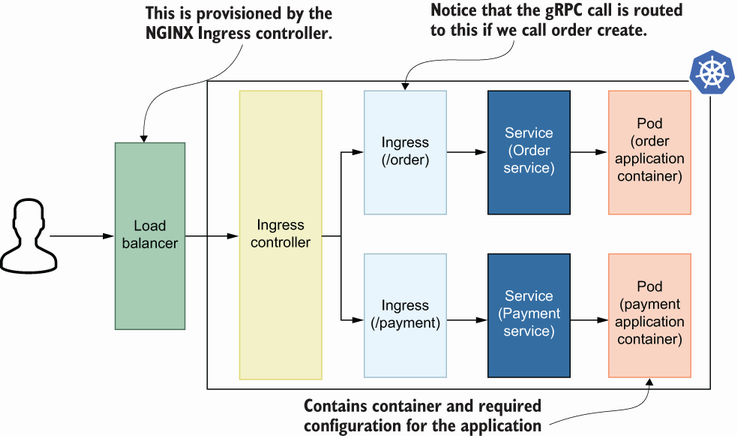
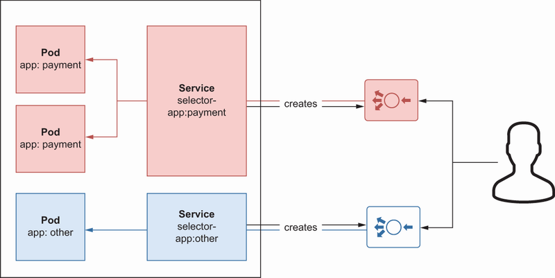
Like other resources, Service has name and label fields for basic metadata. It also has a spec field for mapping a pod and Service using selectors. It also contains port information for routing traffic from a public user to a specific pod. You can also see a flow in which multiple Services route traffic to multiple pods using selectors (figure 8.6). Since we use the type LoadBalancer here, Kubernetes will create a load balancer in the cloud provider with its internal cloud plug-ins.
The first load balancer is created by Service with the app:payment selector. That means the request to that load balancer will be routed to a pod with the label app:payment. In the same way, once a request is made to a second load balancer, it will be routed to a pod with the label app:order because a Service creates that load balancer with the selector app:order.
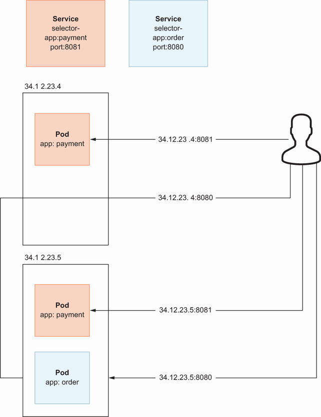
If we want to expose these two services to the public using NodePort, the following flow explains our use case: We simply bind a port in all worker nodes for a specific pod in this flow. It does not matter which worker node’s IP address you use. If you use the IP:port pair, of which IP is one of the IP addresses of the worker nodes, the traffic will be routed to the correct pod, as shown in figure 8.7.
In NodePort Service, to access a specific service, refer to a port by visiting any worker node. As shown in figure 8.7, once a user requests the first worker node, the request is proxied to the second worker node since the pod behind the Service is located in the second worker node. Notice that, with NodePort usage, you need to know the public IP addresses of the worker nodes if you are trying to access pods from outside of the Kubernetes network.
A specific pod can have outside exposure with LoadBalancer or NodePort service types. With LoadBalancer, a cloud load balancer is created, and with NodePort, a specified port is reserved for that service in worker nodes. Would it be valuable to create a LoadBalancer for each microservice to expose to the public? Let’s answer this question by checking the internals of the Ingress controller.
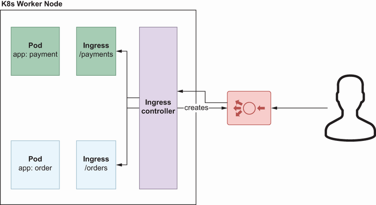
The NGINX Ingress controller helps you create one load balancer per Ingress controller and has a dedicated resource Ingress that helps traffic routing between the end user and a pod. If you create three Services with LoadBalancer type for three microservices, the controller will create three load balancers, one each. If you deploy the controller and create an Ingress resource for traffic routing, you will have just one load balancer instead of three. That one load balancer will be responsible for handling all the traffic between the end user and the pod.
NGINX Ingress plays a key role in routing the traffic from the load balancer to actual pods. The logic behind this is very simple: whenever you create an Ingress resource, the Ingress controller detects this change and refreshes the nginx.conf file with new paths inside the controller. Let’s look at the Ingress resource for the Order service:
apiVersion: networking.k8s.io/v1
kind: Ingress
metadata:
  annotations:
    kubernetes.io/ingress.class: nginx
    nginx.ingress.kubernetes.io/backend-protocol: GRPC   ❶
    nginx.ingress.kubernetes.io/ssl-redirect: "true"     ❷
    cert-manager.io/cluster-issuer: selfsigned-issuer    ❸
  name: order
spec:
  rules:
    - http:
        paths:
          - path: /Order                                 ❹
            pathType: Prefix
            backend:
              service:
                name: order
                port:
                  number: 8080
  tls:
    - hosts:
        - ingress.local                                  ❺
❷ gRPC, by default works on HTTPS.
❹ Context path for the Order gRPC
The Ingress resource has name and label fields like other Kubernetes resources, and most of the configurations are done via the annotation section. This is followed by some rule patterns in which the route operation is applied to a specific path (e.g., backend protocol, certificate issuer, and SSL redirect).
To deploy the Ingress controller, you can use the helm package manager (https://helm.sh/) to deploy the nginx-ingress chart:
helm repo add ingress-nginx https://kubernetes.github.io/ingress-nginx   ❶
helm repo  update #B                                                     ❷
helm install nginx-ingress ingress-nginx/ingress-nginx                   ❸
❶ Adds the required repository for the chart
❷ Updates the repository index
❸ Installs resources via the chart
This will simply deploy an nginx instance inside a pod, creating a load balancer. Whenever you request this load balancer, it goes through the NGINX pod, which also contains nginx.conf. NGINX configurations are rerendered whenever there is a change for any Ingress resource.
In sum, we deployed a pod that contains the actual workload, in our case, any microservice. Then we learned how to manage replicas of that pod and automatically handle image updates. We used Service to expose the pod to the public using Service with the LoadBalancer, NodePort, and ClusterIP options. Finally, we tried to understand the benefits of using the NGINX Ingress controller, which provisions a load balancer and then uses Ingress resources to configure routing for public access. Now that we understand how the public traffic reaches the pod in the Kubernetes environment, let’s look at how TLS certification automation is handled, as we also need it for Ingress resources.
We already addressed how TLS-enabled communication works for gRPC microservices and followed a step-by-step explanation of TLS certification generation for secure gRPC communication. In this section, we will automate this process via cert-manager (https://cert-manager.io/docs/), a tool that helps us obtain, renew, then use certificates in the Kubernetes environment. cert-manager provides custom CRDs (custom resource definitions), which are responsible for certificate-related resources and for integrating third parties to obtain certificates. Vault (https://www.vaultproject.io/) and Let’s Encrypt (https://letsencrypt.org/) are examples of cert-manager integrations, but we will use a self-signed certificate to explain concepts in the local Kubernetes cluster. Let’s look at the custom resources cert-manager provides and apply the integration to see it in action for the Order service.
cert-manager contains custom resources for generating and injecting certificates to specific workloads. Installation will create custom resources in Kubernetes that we can use in our deployment pipeline. There are several options to install cert-manager: Helm, Operator, or kubectl apply. Let’s use Helm:
helm repo add jetstack https://charts.jetstack.io   ❶
helm repo update                                    ❷
helm install \
  cert-manager jetstack/cert-manager \
  --namespace cert-manager \
  --create-namespace \                              ❸
  --version v1.10.0 \
  --set installCRDs=true                            ❹
❷ Updates the repository index
❸ Creates a namespace if it does not exist
You can verify and see all the available CRDs installed via cert-manager as follows:
kubectl get crds
As a result, you will see six CRDs: CertificateRequests, Certificates, Challenges, ClusterIssuers, Issuers, and Orders. We will focus on ClusterIssuers. Let’s create a ClusterIssuer to handle the self-signed certification flow, which is very handy for local development.
I find this resource name (ClusterIssuer) significant because when you want to use a certificate for TLS communication, you must “issue a certificate.” ClusterIssuer does that for you cluster-wide. You would use the following resource to create a self-signed certificate in a Kubernetes cluster:
apiVersion: cert-manager.io/v1
kind: ClusterIssuer
metadata:
  name: selfsigned-issuer
spec:
  selfSigned: {}
As always, save this content in cluster-issuer.yaml and use the following to create this resource in Kubernetes cluster:
kubectl apply -f cluster-issuer.yaml
You can verify creation with this command:
kubectl get clusterissuers -o wide selfsigned-issuer
Now that we have a valid certificate in the Kubernetes cluster, let’s use it in one of our Ingress resources.
The self-signed certificate we created is only authorized for local development and uses Ingress’s .local domain name. Add the following record to /etc/hosts:
ingress.local 127.0.0.1
We use 127.0.0.1 here since, at the end of this section, we will make our first microservices request via a tunnel provided by the minikube tunnel command. Notice that we already visited the Ingress configuration for the Order service in section 8.2.7; now we will extend it to configure TLS communication:
apiVersion: networking.k8s.io/v1
kind: Ingress
metadata:
  annotations:
    kubernetes.io/ingress.class: nginx
    nginx.ingress.kubernetes.io/backend-protocol: GRPC
    nginx.ingress.kubernetes.io/ssl-redirect: "true"
    cert-manager.io/cluster-issuer: selfsigned-issuer    ❶
  name: order
spec:
  rules:
    - http:
        paths:
          - path: /Order
            pathType: Prefix
            backend:
              service:
                name: order
                port:
                  number: 8080
  tls:
    - hosts:
           - ingress.local                               ❷
❶ Configures a certificate for this Ingress
❷ TLS configuration is authorized for this domain.
As you can see, certificate configuration is handled by annotations, a widely used technique to extend resources’ capabilities. Now we have certificates in place, they are issued, and Ingress is configured to work with them. Notice that the certificates are not by default available to any client. Let’s look at how to handle certificate management on the client side to create a secure connection between the gRPC client and the gRPC server.
minikube has an available command, minikube tunnel, that creates a proxy through 127.0.0.1 so that whenever you request 127.0.0.1, that request will be proxied to the Ingress controller inside minikube. Let’s create a tunnel:
minikube tunnel
Open your browser and request https://ingress.local to see if you will get a certificate issued. You can simply click the padlock/info icon in the browser next to the insecure message and download the certificate. If you double-click on that certificate, it will prompt you to install the certificate into your key chain. Refer to http://mng.bz/zXZg for detailed steps on how to collect the certificate from the browser.
You should see a secure connection after installing the certificate. We are requesting a browser, but this is not a gRPC communication. To make a gRPC call, we can still use grpcurl and provide the .proto files to understand what kind of methods are available to grpcurl for the requested service:
grpcurl -import-path /path/to/order -proto order.proto ingress.local:443
➥ Order.Create
In previous chapters, we handled those .proto files; locate them on your computer and pass the folder’s full path to the grpcurl command with the parameter -import-path and -proto file. Now grpcurl knows the methods to construct correct request metadata for the gRPC call. Notice that we don’t need .proto files for the programmatic approach. For example, if you want to call the Order service via a Go client, adding .proto files as a dependency and using client functions to call specific services is enough.
We started with creating a pod and exposing it to the public via the Service resource. Using the LoadBalancer Service type seemed straightforward, but it may not be efficient for microservices because we end up with lots of load balancers, which is not cost-effective. Then we used the Ingress controller to handle routing with Ingress resources, and the controller became our single-entry point as a load balancer. Finally, we managed our certificates with a cert-manager, as gRPC only works with HTTPS over HTTP/2. Now that we understand how to complete a simple deployment into a Kubernetes cluster, let’s look at advanced deployment strategies we can use in microservices deployments.
Deploying to Kubernetes is not a one-time operation; it is an operation that is integrated into a CD pipeline that updates the container image artifact once we want to make changes in the actual workload. This is mostly done by updating the image version, but it can also be done by updating the environment variables of pod containers or by changing replicas of a deployment. You will hear about RollingUpdate, Blue-Green, or Canary deployment while searching the internals of Kubernetes deployment. Let’s look at each of these deployment strategies with real-life examples.
RollingUpdate is a deployment strategy in which a new ReplicaSet is created for the new version, and the old ReplicaSet is gradually removed until the new one has the correct number of replicas. This is the default behavior of a deployment in Kubernetes (http://mng.bz/0KQW). Assume that we have huseyinbabal/order:1.0.0 in our deployment, and you want to deploy a new version of 1.1.0. You can trigger a rolling update with the following command:
kubectl set image deployment/order order=order:1.1.0
Here, we simply update the deployment and change the order container to use a new image (figure 8.9).
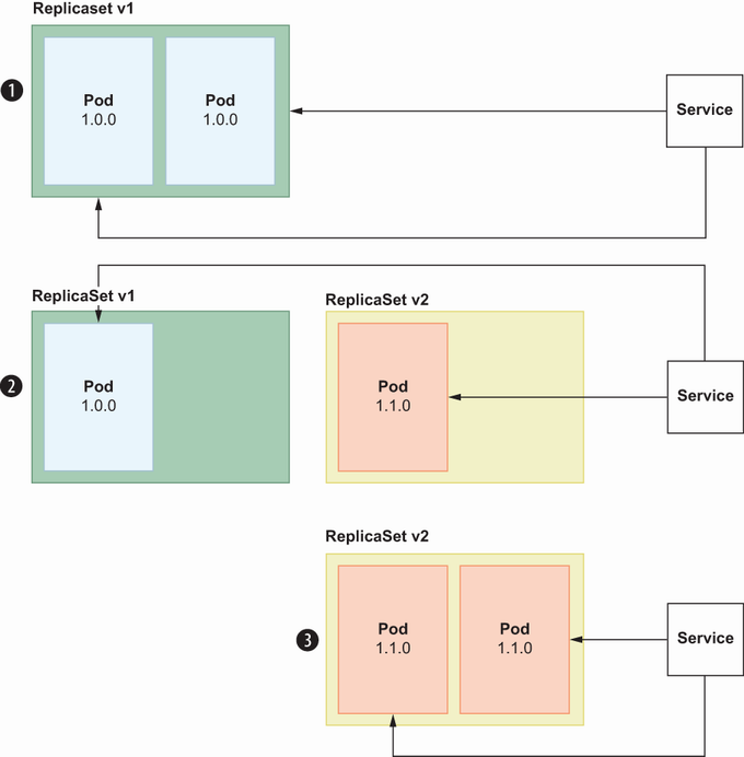
As you can see in figure 8.9, RollingUpdate is completed in three steps:
Service proxies traffic to two pod instances under ReplicaSet v1.
Once the image is updated for deployment, it creates Replicaset v2 and assigns a new pod to this ReplicaSet.
Meanwhile, one pod is removed from ReplicaSet v1 because having two replicas works for us. Service proxies traffic to the pod in ReplicaSet v1 and ReplicaSet v2.
ReplicaSet v2 has two available pods, and all the pods under ReplicaSet v1 are removed. Finally, Service proxies all the traffic to the pods under ReplicaSet v2, which contains a new Docker image version.
It does not take much time to complete a RollingUpdate, and in this interval, v1 pod and v2 pod may be available at the same time. Here, you can clearly see that it is crucial to develop a system that is always backward compatible so that once we roll back our deployment to v1, the system should continue to work without any data inconsistency or downtime. Now that we understand RollingUpdate, let’s look at the next strategy: Blue-Green deployment.
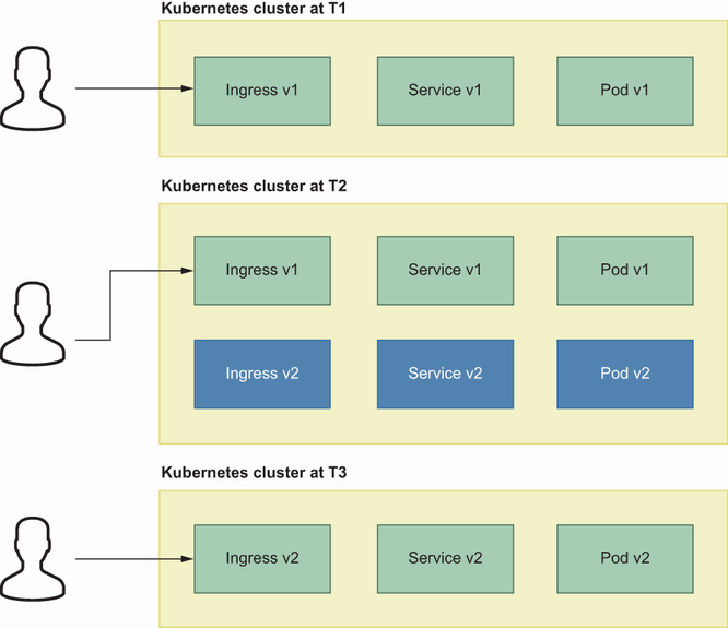
In this type of deployment strategy, there are two versions of the existing system, and whenever a deployment occurs on one of the systems, the old one becomes deprecated by routing traffic to the new system. We currently have Payment Service v1 in production and plan to deploy v2 soon. However, this time it will not be like an almost-instant update like in RollingUpdate; v2 will be prepared in advance, and traffic will be switched to v2 after everything is taken care of. In this case, we start with Green (v1), and when v2 is deployed, it is Blue at the beginning, but after a while will be Green. You can see the deployment transitions in figure 8.10.
Figure 8.10 shows the overall picture of blue-green deployment, but what happens under the hood is this:
Remember, once we create an Ingress controller, it provisions a load balancer, and we add Ingress resources behind this controller using the Ingress name.
For the blue environment, an additional Ingress controller can be deployed, and Ingress v2 can be involved behind the load balancer created by the new Ingress controller.
The current state is our domain has a record pointing to the initial load balancer (green), and once we feel confident, we simply update the record value as the second load balancer.
Once we introduce a new version, it is deployed behind the first load balancer and becomes green after an internal check.
Most of the time, blue environments are accessible from the internal network so that they can be tested by internal employees or a particular group of testers.
This deployment strategy is smoother since we simply change the load balancer switch. However, since we duplicate the existing system entirely as v2, it will introduce an additional cost.
Now that we understand Blue-Green deployment, let’s look at canary deployment.
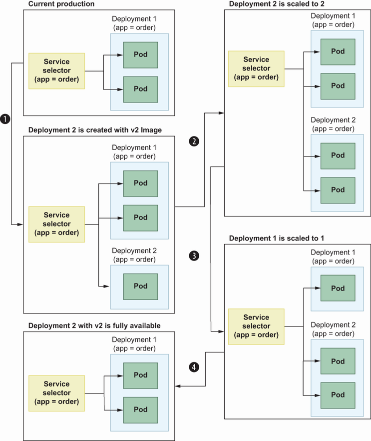
Remember that a Service resource is designed to expose a pod as an endpoint internally or publicly to users. The Service–pod relationship is handled by selectors in the Service resource so that Service uses a selector field to find available pods filtered by the logic inside the selector. In canary deployment, there is always one service, but this time an additional deployment is created with new data (e.g., a new Docker image) but with the same selector. Then, requests are distributed between v1 and v2 pods. In canary deployment, this percentage is gradually changed until all the replicas become available in the new deployment and the old one is downscaled to zero (figure 8.11).
In figure 8.11, you can see the transitions for canary deployment, which are simply a summary of gradually increasing the possibility of seeing the newly deployed feature while deprecating the old deployment. We need a second deployment here with the same selector so that once the request reaches the load balancer, it will be routed to a pod by selectors. Canary deployment is widely used, especially for collecting feedback from end users by enabling an experimental feature to a subset of customers instead of overwriting the current production.
To better understand deployments, we used a traditional approach to deploy a workload to the Kubernetes environment by kubectl. However, multiple options exist to automate this process within the GitOps context. ArgoCD (https://argo-cd.readthedocs.io/en/stable/) and FluxCD (https://fluxcd.io/) are famous examples of GitOps notation; you can connect them to the repository, and whenever you push a change to this repository, they handle deployments for you.
We saw how to use cert-manager for local development to set up a proper self-signed certificate generation and inject it to enable TLS for Ingress resources. cert-manager is so powerful you can integrate it with well-known certificate managers, such as Let’s Encrypt and Vault. You can even integrate cert-manager with Cloudflare so that TLS will be handled on Cloudflare, and necessary configurations will be applied to it. These kinds of seamless integrations are important for implementing business logic and not disturbing manual infrastructure operations.
If you want to inject confidential data into workloads like pods, you can use Kubernetes secrets. You can even use ExternalSecrets (https://external-secrets.io/v0.7.0/) to maintain your secrets in a third-party tool.
Building a cloud-native application is important for productivity, as this helps you ship products within containerized applications.
Kubernetes has good abstraction on top of cloud technologies in which you manage components through resource declaration. Kubernetes will take care of container orchestration and create necessary components in the cloud.
Deployment involves deploying services, CronJobs, and so on and handling certification for TLS communication between the end user and services. cert-manager makes the process smoother with predefined CRDs to create, regenerate, and issue certificates.
Kubernetes is a good platform for applying deployment strategies such as RollingUpdate, Blue-Green, and canary. RollingUpdate is the default deployment strategy in which pods are gradually updated until they all have up-to-date resource descriptions. Blue-Green works as a switch, and canary is good for showcasing experimental features to end users for a specific time.